Modern technology demands seamless integration and communication between electronic systems, and the CAN bus cable plays a central role in this context. As an essential component of digital networking, the CAN bus cable is instrumental in ensuring efficient communication between cars and other devices. This article provides a comprehensive exploration of can bus wires, covering their definition, design, and connector types. By unraveling the technical aspects and practicalities of canbus electrical cables, we equip you with the knowledge for production and connection.
What is CAN Bus Cable?
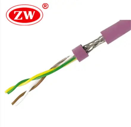
CAN bus cable, short for Controller Area Network Bus cable, is a high-speed network communications cable for vehicles and industrial automation systems, allowing microcontrollers and devices to communicate with each other without a host computer. Bus can cable is designed following CAN Open and ISO 11898 standards for high reliability, flexibility, and efficient use of network bandwidth. Flexible CAN bus cables are abrasion- and cut-resistant, and are typically twisted-pair to provide common-mode noise immunity.
Although CAN bus cables originated in the automotive field, they are now widely used in other areas such as smart sensors, underground communications, public transportation, fire protection networks, and smart homes due to their immunity to interference and long-distance transmission capabilities. However, the maximum transmission length of bus cables can vary depending on the cable types and operating speed, for example, standard CAN cables operating at speeds up to 1 Mbps have a maximum distance of 40 meters, and a reach of up to 10 kilometers (set at 5 Kbps).
With bus cables out of the way, let’s take a look at the can bus system, including the number of wires contained therein.
How many wires are in a CAN bus?
Controller Area Network (CAN) belongs to the category of fieldbus, a serial communication network that enables distributed control systems, integrating the cost, scalability, and fault tolerance in one, which was developed by Bosch in Germany in the 1980s specifically for the automotive industry. Modern vehicles contain a variety of systems and computer components, often referred to as electronic control units or ECUs. CAN is the electronic “brain”, allowing ECU to communicate with each other; and CAN bus is the control signal transmission line.
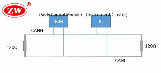
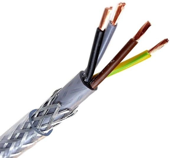
Contrary to what one would expect from such a complex system, the standard CAN bus cable consists of only two wires: CAN high and CAN low. These are differential wires, usually configured as twisted pairs, characterized by a 120-ohm impedance and working in series to transmit and receive data. Automotive can bus cable color codes are yellow (CANH) and green (CANL). Common can bus cable specifications are 18, 20, and 22 AWG can bus cable. When the CAN bus is in idle mode, both lines carry 2.5V. During the data bit transmission, the CAN high line goes to 3.75V, and the CAN low drops to 1.25V, thereby generating a 2.5V differential between the lines. When they don’t create the expected differential voltage during transmission. This may indicate an error in transmission, triggering error handling protocols to maintain system integrity. Additionally, In addition, there may be a ground wire, a CAN bus cable with power, or an additional function wire.

Next, we shall examine the connectors that interface these wires.
What type of connector is a CAN bus?
CAN bus (Controller Area Network bus) system primarily uses a two-wire, half-duplex, high-speed network technology for critical, efficient communications within various applications. The connectors used in CAN bus systems vary based on the data transfer rates, environmental conditions, and space constraints.
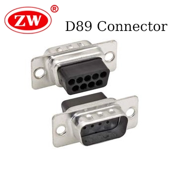
The predominant can bus connectors employed in Controller Area Network (CAN) systems encompass the DB9 connector, renowned for its extensive application across numerous CAN bus interfaces, and the OBD-II (On-Board Diagnostics II) connector, which serves as the standardized access point for CAN bus in automotive applications. In marine settings, particularly within NMEA 2000 networks, Micro-C and Mini-C connectors are frequently utilized, catering to the specific demands of this environment. For industrial applications, where exposure to harsh environmental conditions, ruggedized connectors such as the M12 type are often preferred due to their enhanced durability and reliability. Additionally, in scenarios like prototyping or situations with less stringent requirements, terminal blocks offer a simpler and more accessible connection solution.
The choice of connector is crucial for ensuring proper network termination and secure, uninterrupted connections, and should therefore be accurately selected for the specific application.
Following this, let’s take a closer look at the technical configuration of the CAN bus wire to see if the wires within this network must be in a twisted pair configuration and can bus cable types.
Do CAN bus wires have to be twisted?
Yes, the twisted pair design is a key feature in the robustness and reliability of CAN bus communication. Twisting the wires in a CAN bus system is not just a standard practice but a necessity:
- Noise Cancellation: In a twisted pair, each wire is exposed to a similar level of interference, Since the CAN bus is a differential system, the common-mode noise (the noise that appears equally on both wires) is largely canceled out.
- Signal Integrity: The twisted pair maintains a consistent physical distance between the two wires, which helps in maintaining the characteristic impedance of the cable, reducing signal reflections and crosstalk, ensuring better signal integrity over longer distances.
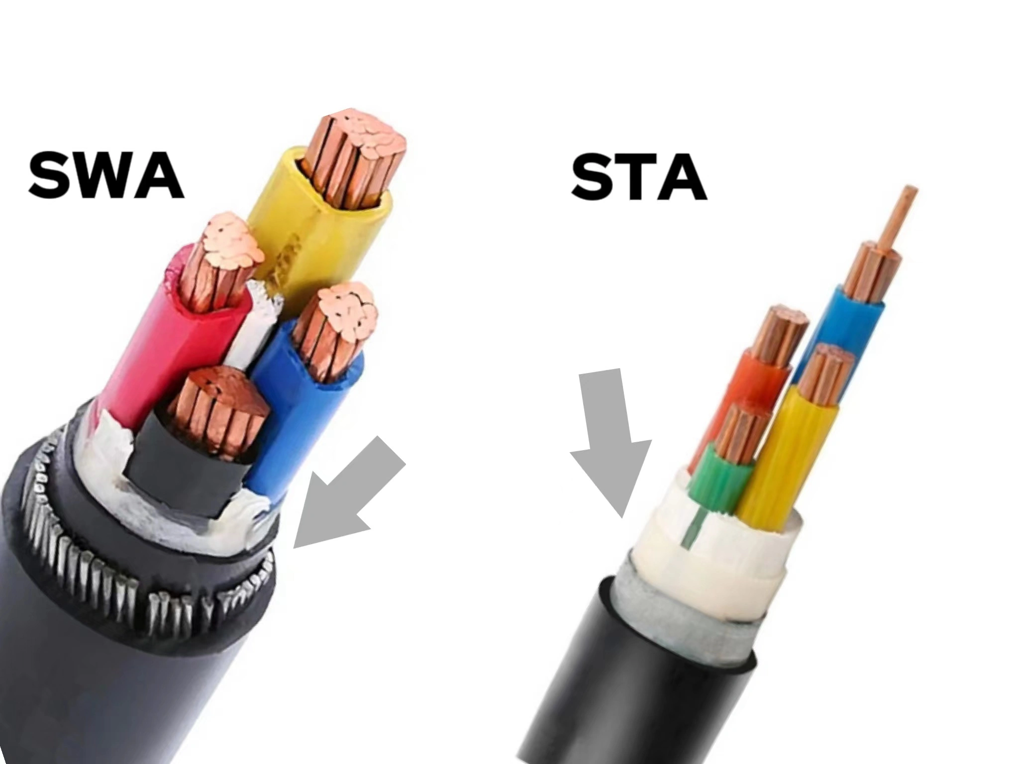
CAN bus twisted wire is available in shielded or unshielded varieties. Shielded cable (J1939 11 cable) provides shielding from static interference. For vehicles with multiple electrical systems running over CAN bus, shielded cable is advisable. For applications with few connections or short wire runs, unshielded cable (designated J1939/15) may be adequate.
In summary, the twisted pair design in CAN bus systems plays a critical role in reducing electrical noise and maintaining signal quality, making it the preferred choice for reliable communications over long distances. Finally, as an expert in cable manufacturing, we will explain the production process of 2 wire can bus.
How to make a can bus cable?
The production of data bus cable involves a series of steps to ensure that the final product meets the standard for effective communication within CAN systems. This process includes:
Step 1. In the manufacturing process of bus cables, it is imperative to first identify the specific bus standards, such as CAN bus, Profibus, CANopen, or Modbus, due to their distinct requirements for impedance, data rate, and connector types.
Step 2. Wire and cable materials are then selected according to environmental conditions and electrical requirements, usually copper with excellent conductivity and insulation like PVC. Precisely measure and control the diameter of the wires during the drawing process to ensure they remain within specified tolerances.
Step 3. During assembly, precisely twist the wires at specified intervals to balance impedance and reduce interference, use filler if necessary to maintain shape and flexibility, and add integral shielding such as braided copper or aluminum foil for further EMI protection.
Step 4. The cable is then encased in a durable PVC outer sheath to withstand environmental challenges. Finally, the cables are checked for electrical continuity, insulation resistance and impedance to ensure compliance with CAN bus standards and to obtain the relevant certifications, such as CE marking, 3c certification, and IEC standard.
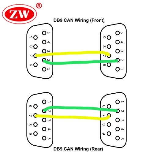
Some of you may be wondering how the bus is terminated or can bus cable connection. In general, the easiest way to wire the bus wire is to make a straight-through connection between pin 2 and pin 7 on the DB9 connector. As shown in the canbus wiring diagram below. Additionally, CAN bus cable must be terminated at both ends by resistors that represent the characteristic impedance of the communication protocol — typically 120 ohms. In today’s market, most connectors for CAN bus come with built-in termination resistors.
Bottom Line.
To conclude, twisted pair can bus plays an integral role in modern communication networks due to their simplicity, affordability, fault tolerance and efficiency, especially in automotive and industrial applications. Understanding its structure and function, including the typical two-wire system and the necessity of twisted pairs, and how to connect it is essential for seamless communication. Manufacturing CAN bus cables requires careful consideration of these factors, as well as meticulous assembly and testing to meet exacting standards. When selecting CAN bus cables, considering a reputable supplier like ZW Cable ensures quality and reliability, giving you peace of mind when working with a critical component of your network infrastructure.