
Control Cable Types Description
Multicore Control Cables, SY,Cy & YY Cable
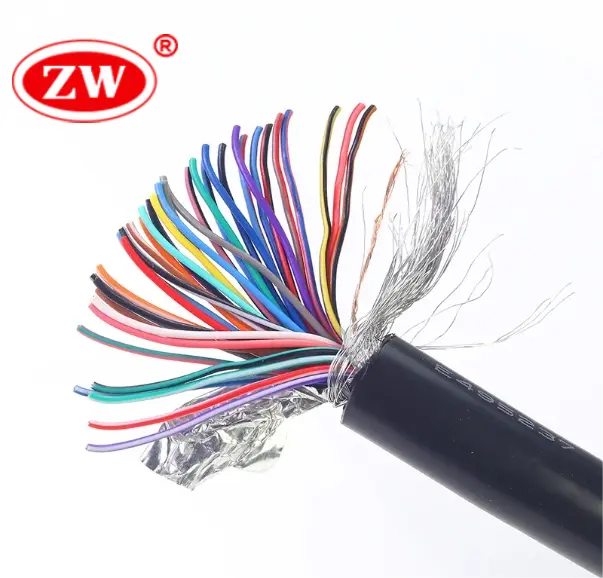
Control cables are made of one or more wires, usually is copper conductor. SY and YY Cables are used in the industrial and mining industries. AC voltage for control wire is 450/750 volts. Control wires are produced with polyvinyl chloride insulation and a PVC Sheath.
Conductor Type
Number of Cores
+ Show More
Shielding
Jacket
Multicore Control Cables, SY,Cy & YY Cable
Control cables are made of one or more wires, usually is copper conductor. SY and YY Cables are used in the industrial and mining industries. AC voltage for control wire is 450/750 volts. Control wires are produced with polyvinyl chloride insulation and a PVC Sheath.
Conductor Type :
Number of Cores :
Shielding :
Jacket: PVC
Conductor Type :
Number of Cores :
Shielding :
Jacket: PVC
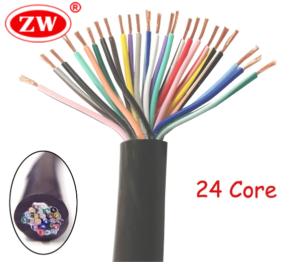
Conductor Type :
Number of Cores : 16 Cores
Shielding :
Jacket: PVC
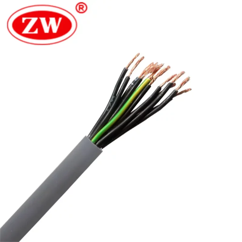
Conductor Type : Stranded
Number of Cores : 12 Cores
Shielding : Shielded
Jacket: PVC
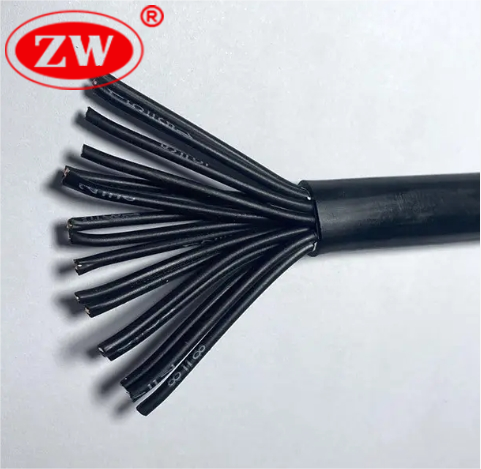
Conductor Type : Stranded
Number of Cores : 8 Cores
Shielding :
Jacket: PVC
Load More
Control Cable Latest Article
Additional Information:
Types of electrical control cables
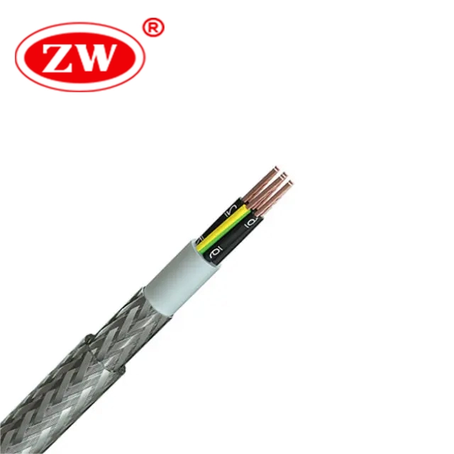
- SY cable: A flexible, PVC-insulated, galvanized steel wire braided control cable, suitable for industrial automation and machinery control applications.
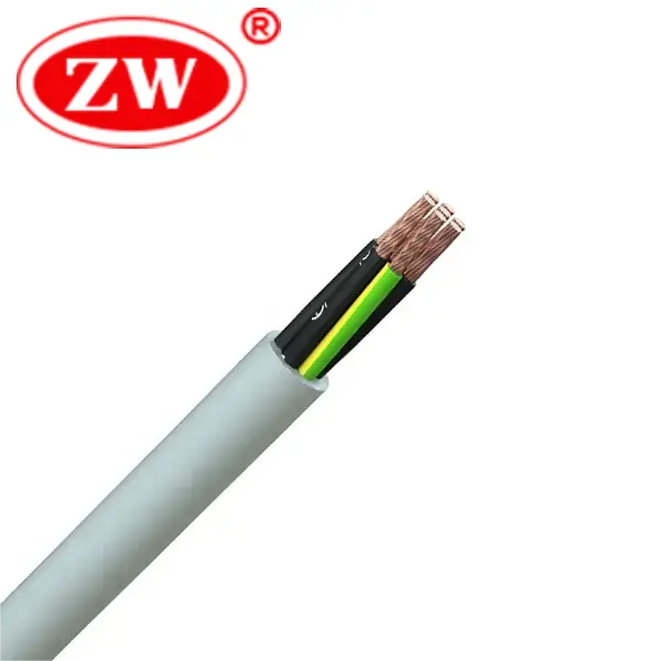
- YY cable: A multi-core, PVC-insulated control cable without shielding, commonly used for signal transmission and control in various indoor applications.
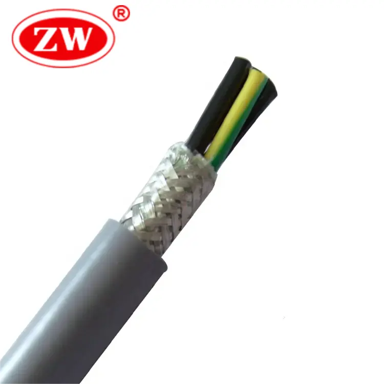
- LiYCY cable: A shielded control cable with PVC insulation designed for data transmission and control purposes in industrial environments with potential electromagnetic interference.
- LiYY cable: An unshielded, PVC-insulated control cable, often utilized for internal wiring of electrical equipment and appliances where shielding is unnecessary.
- CY Cable: A flexible control cable with tinned copper wire braiding for enhanced shielding, ideal for areas with high electromagnetic interference and noise.
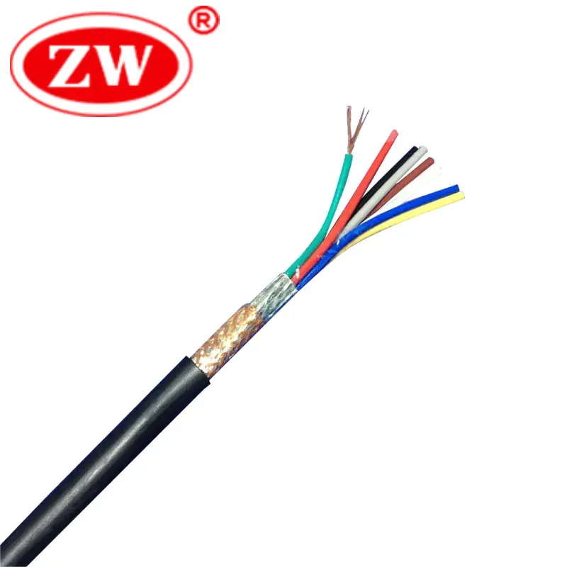
- RVVP Cable: A shielded flexible cable with PVC-insulated sheath and overall copper wire braided, commonly used for transmitting control signals, data, and power in industrial and commercial applications.
What is Control Cable HS Conde?
Hs code for control cable is 8544492100